 An inductor is a passive two terminal electrical component
will resist the change of flow of the electrical current through it. It also
named as a coil or a reactor. The inductor is naturally a conductor which
turned to in the form of coil which stores the energy temporarily when current
flows through it by creating a magnetic field. When the current flow changes in
the inductor the magnetic field will induce a voltage in it, by the Faraday’s
law of electromagnetic induction it opposes the change in current created on
it. This property is called the inductance and the unit is henries (H). The operation of the inductor is that it will
block the flow of AC when it passes the DC. Inductors are widely used in tuned
oscillators ant in
An inductor is a passive two terminal electrical component
will resist the change of flow of the electrical current through it. It also
named as a coil or a reactor. The inductor is naturally a conductor which
turned to in the form of coil which stores the energy temporarily when current
flows through it by creating a magnetic field. When the current flow changes in
the inductor the magnetic field will induce a voltage in it, by the Faraday’s
law of electromagnetic induction it opposes the change in current created on
it. This property is called the inductance and the unit is henries (H). The operation of the inductor is that it will
block the flow of AC when it passes the DC. Inductors are widely used in tuned
oscillators ant in 
Friday, April 4, 2014
Inductor
An inductor is a passive two terminal electrical component
will resist the change of flow of the electrical current through it. It also
named as a coil or a reactor. The inductor is naturally a conductor which
turned to in the form of coil which stores the energy temporarily when current
flows through it by creating a magnetic field. When the current flow changes in
the inductor the magnetic field will induce a voltage in it, by the Faraday’s
law of electromagnetic induction it opposes the change in current created on
it. This property is called the inductance and the unit is henries (H). The operation of the inductor is that it will
block the flow of AC when it passes the DC. Inductors are widely used in tuned
oscillators ant in Crystal Oscillator

The crystal oscillator is an oscillating circuit that uses the mechanical resonance produced by a vibrating crystal of piezoelectric material to produce the electrical signal having the stable frequency. Because of its stability in producing frequency which is used to provide clock signal for digital circuits, used in quartz wrist watches for tracking the tome, to stabilize the frequencies of radio transmitters and receivers. The oscillator circuits which containing the crystal named crystal oscillatory circuits. The most common used piezoelectric crystal is quartz crystal.

The frequency range of kilohertz to hundreds of
megahertz is manufactured by with help of these quartz crystals. As say above
the most applications of these crystals are used in cellphones, computers,
radios, clocks, wristwatches, signal generators and in oscilloscopes
Capacitor
 The capacitor is a passive two terminal electrical component
which is used to store the electrical energy electrostatically in an electric
field. The mechanism is used to store the energy is that two electrical plates
are separated by a dielectric. When a capacitor is connected across a voltage
source for a sufficient time it will not pass any current through it. But it
will charge to the potential between its plates. Here one plate is act as a +ve
plate and another is –ve plate. The unit of the capacitance is farads. The
capacitor will block the DC but passes the AC. The main applications of the
capacitors are used in analog filter networks, for smoothing the output of the
power supplies, and in resonant circuits for fine tuning of frequencies.
The capacitor is a passive two terminal electrical component
which is used to store the electrical energy electrostatically in an electric
field. The mechanism is used to store the energy is that two electrical plates
are separated by a dielectric. When a capacitor is connected across a voltage
source for a sufficient time it will not pass any current through it. But it
will charge to the potential between its plates. Here one plate is act as a +ve
plate and another is –ve plate. The unit of the capacitance is farads. The
capacitor will block the DC but passes the AC. The main applications of the
capacitors are used in analog filter networks, for smoothing the output of the
power supplies, and in resonant circuits for fine tuning of frequencies.
The capacitance C of the capacitor is characterized by the
ratio of applied charge ±Q and the voltage across the conductors. That
is C=Q/V. The working of the
capacitor is that it charges with the charge of source and it discharge through
the path which it would grounded. This charging and discharging of the
capacitor will make it as favorable for oscillators and integrator's.
Saturday, March 29, 2014
Resistors
A resistor is a passive electronics component that uses to provide electrical resistances on a circuit. Its main functions are to reduce the current flow on serial and reduce the voltage when it is connected parallel. Mainly two types are named fixed resistances and variable resistances. Here the fixed resistance named simply resistor and the variable resistances are named thermistors, varistors, trimmers,photoresistors and potentiometers.
 The current through the circuit can be calculated by Ohm's law, that is, I= V/R.
Where I is the current flows through the resistor in amperes, V is the potential difference across the resistor in volts and R is the resistance provided by the resistor in ohms.
The current through the circuit can be calculated by Ohm's law, that is, I= V/R.Where I is the current flows through the resistor in amperes, V is the potential difference across the resistor in volts and R is the resistance provided by the resistor in ohms.
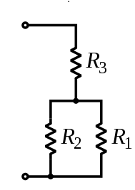
- The resistors can be connected serially which will add the resistance according to the resistances but will reduce when parallely connected. Which can shown in the below figures and equations.
- For Serial connection


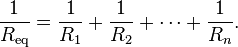
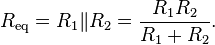
- For Parallel connection

- For serial + Parallel connection

Subscribe to:
Posts (Atom)